Considering I haven’t sent the finished model to be vetted by the Professor who runs the rapid prototyping machine, this can only be the first part of hopefully a short series.
To continue my quest to use laser scanning to model and then reproduce important fossils, I was given a sample dataset to format correctly and then send over to the Mechanical Engineering Department to test out their rapid prototyping machine. This dataset is a landscape model (I believe based on a DEM) made of point data in an XYZ file. To explain, the surface is made up of a series of points positioned by x-axis, y-axis, and z-axis triplets. In the end, I needed a solid model in *.STL format. Although I was told to use AutoCAD for this, I think I’ve found another (free) way.
I planned to import the data file into the free, open-source point-meshing program Meshlab v. 1.2.3 and manipulate it there, but I needed to change the file format correctly first. Originally, I used the MS-DOS program xyz2vrml.exe (from this useful site) to convert the data text file into a *.WRL (VRML) file, but then I realized I could just change the file extension and Meshlab would be able to read and import the points (this of course only works if your data file just has a different extension than Meshlab expects, not if the data are a different type).
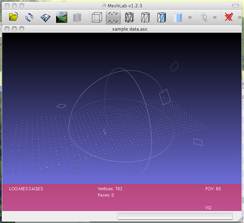 |
| Adding point landscape data to Meshlab. |
To convert the point data to a mesh (TIN) surface, I used the Surface Reconstruction: Ball Pivoting filter (in the Remeshing, simplification and reconstruction menu) with the default settings (world unit: 0.0, perc on 0.0, clustering radius: 20, angle threshold: 90). To see the result I had to click the Wireframe button in Meshlab to get a surface made of triangles. The file was saved in *.3DS format.
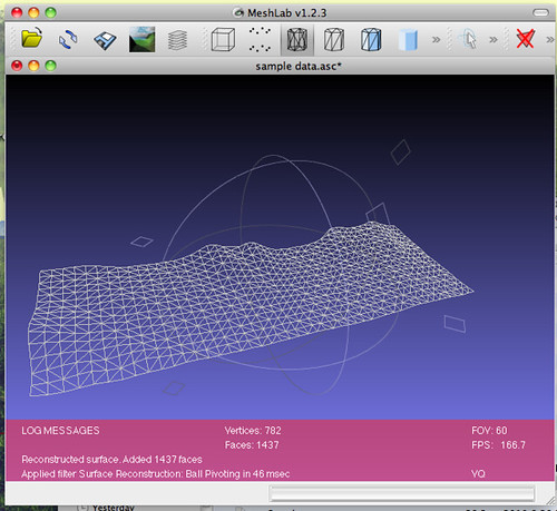 |
| Wireframe after meshing. |
The *.3DS file was then imported into Google Sketchup for modeling. Although the mesh seemed to act like a single object, attempting to use certain tools made me realize that it was being manipulated as a collection of triangles, which meant I couldn’t use such things as the Push/Pull tool to extrude the surface down to a lower plane to create a solid model. Luckily I found a Sketchup plugin to let me do something similar (available here). The Curviloft plugin allowed me to fill in space between a rectangular base (easily drawn in Sketchup) and the meshed landscape surface above it.
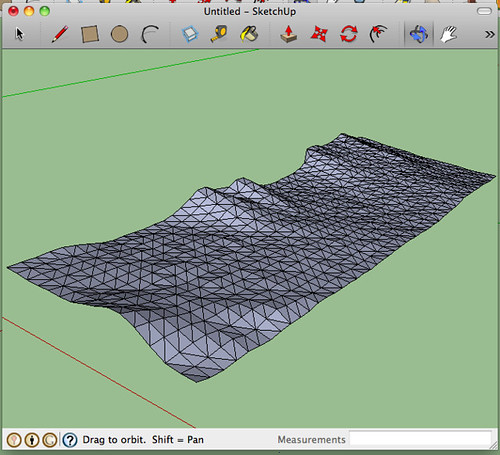 |
| Adding mesh to Google Sketchup. |
I used the Skin Contours tool on each of the four remaining sides to achieve a solid model. To do this, I drew a line connecting the corner of the base rectangle to the corner of the mesh above it. Once a side had been marked this way, I used the Skin Contours tool to select each edge of what the new face was going to be and clicked the checkbox. In order to select adjacent mesh edges, the Extend Selection toolbar button needed to be on, and the Stop Prolongation button needed to be off.
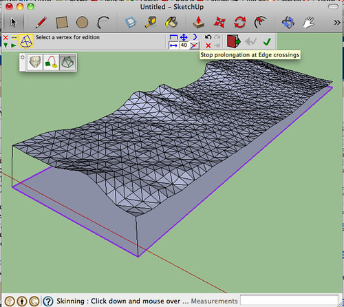 |
| Adding a base and connecting it to the mesh at the corners. |
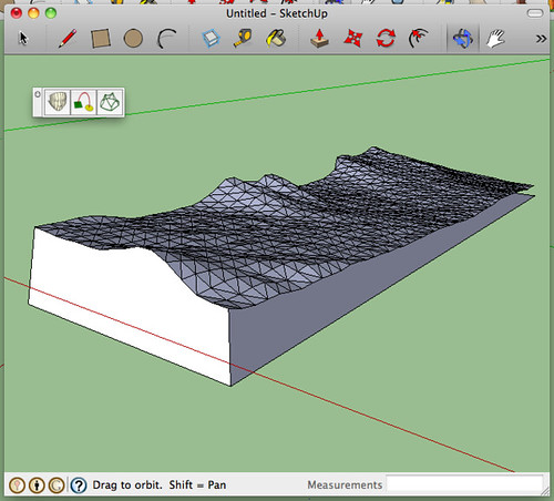 |
| One side completed. |
To get the final file format correct (I’m hoping), I had to export the model from Sketchup as a COLLADA (*.DAE) file, then into Meshlab, and then use Meshlab to save into *.STL. I was told that my *.STL file needs to be “solid,” but I’m not sure whether this simply means “no holes” or whether there is a trick to completely fill the model with some virtual material (Unobtanium? Adamantium?). I’ll send this model to the Professor of Rapid Prototyping (not his real title, unfortunately) and see what sort of feedback he has. Tune in next time for the exciting conclusion!
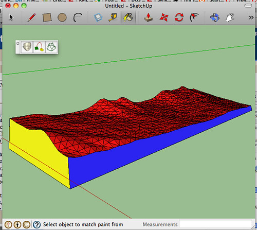 |
| The finished model in Google Sketchup. |
Total project time (including learning Sketchup and Meshlab and designing the workflow): several hours.
Writeup time: 1.5 hours


